There is a close relationship between the drive system and brushless motor characteristics, and various methods have been used to improve the controllability and characteristics of motors. In this post, we will explain two typical drive systems: square wave drive and sine wave drive.
| Motor Drive System |
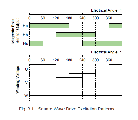
3.1.1 Square Wave Drive System (120° conduction mode)
There are many types of brushless motor drive systems, and the 120° conduction mode's square wave drive is one common example. As shown in Fig. 3.1, this method involves switching the excitation state according to the combinations of hall effect IC output signals. While speed ripples occur during low-speed operation, high output power can be achieved with a simple circuit. Therefore, it is widely used to control brushless motors for office automation equipment and power devices.
3.1.2 Sine Wave Drive System
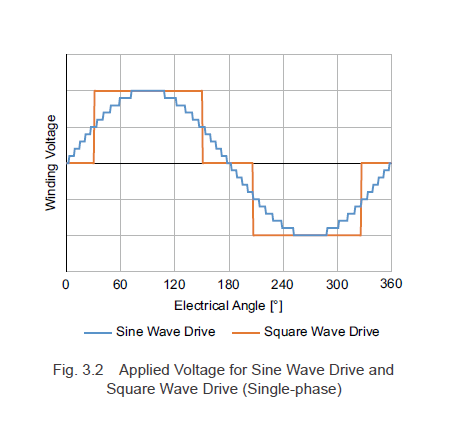
A sine wave drive system is a drive system that exerts fine control over the applied voltage, as shown in Fig. 3.2, to make the motor current sinusoidal. This drive system has a few torque ripples and allows for stable rotation. In addition, it also reduces the noise generated from driving the motor.
However, to perform sine wave driving, it is necessary to accurately detect the rotor magnetic pole positions. Traditionally, a high resolution encoder was required, but this had the disadvantage of increasing the overall length and cost of the motor.
In recent years, rather than use an encoder:
- Software has been used to process the hall effect IC signals.
- Detection has been performed using motor inductance and back EMF.
Thus, it is now possible to detect the magnetic pole positions using various other methods and perform sine wave driving.
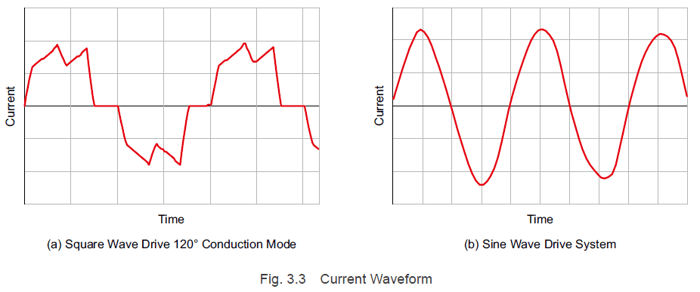
3.1.3. Current Waveforms for Each Type of Drive System
Actual current waveforms are shown in Fig. 3.3. A square wave drive has distortion with respect to applied voltage waveform, and it is actually closer to sine waves in form than square waves. A sine wave drive has a waveform similar to that of applied voltage waveforms.
In the next few posts, we will explain how the drive system can affect the motor's performance.
|
Previous Post
|
Next Post
|


Learn more about Oriental Motor's 
Subscribe (top right corner) to receive monthly updates!