When a voltage is applied to an AC induction motor, it runs at a certain speed. Variable speed requirements for AC induction motors are typically fulfilled by a 3-phase motor and an inverter or VFD. This blog post also introduces another option.
First, let's talk about the most common speed control method for AC induction motors, which is the inverter, or variable frequency drive (VFD). I'm most familar with Fuji Electric's FRENIC Mini C2 Series.
Fuji Electric FRENIC Mini C2 Series VFDs
How does this device control the speed of an AC motor? Let's first understand why a motor would run at a certain speed. In mathematical terms, the synchronous speed of the motor is calculated by:
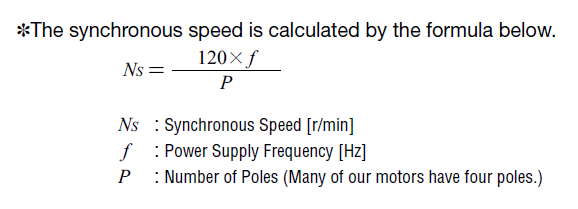
Most industrial AC induction motors are the 4 pole type, so motor speed is synchronized to the input power supply frequency (Hz). At 60 Hz, the motor will run at 1800 RPM.
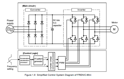
A variable frequency drive controls the motor speed by using PWM (Pulse Width Modulation) to alter the power supply frequency that's fed to the motor. There is typically no feedback coming back from the motor; although some drives uses back EMF as feedback.
Here's a block diagram for control logic of the FRENIC Mini C2 VFD (from the manual). Notice its complexity just with the sheer number of components. Features such as dynamic torque boost or slip compensation control are typically offered to improve performance.
One drawback of using VFDs is that it can get expensive and difficult to size. It also requires a 3-phase AC induction motor with a inverter duty rating, or at least a continuous duty rating. If the motor offers a braking mechanism, it typically reduces the duty cycle. I've seen VFDs for single-phase motors in the market in the past, but they are difficult to find, and we've never tested them with our motors.
Another Way to Control the Speed of Single-Phase AC Induction Motors?
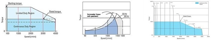
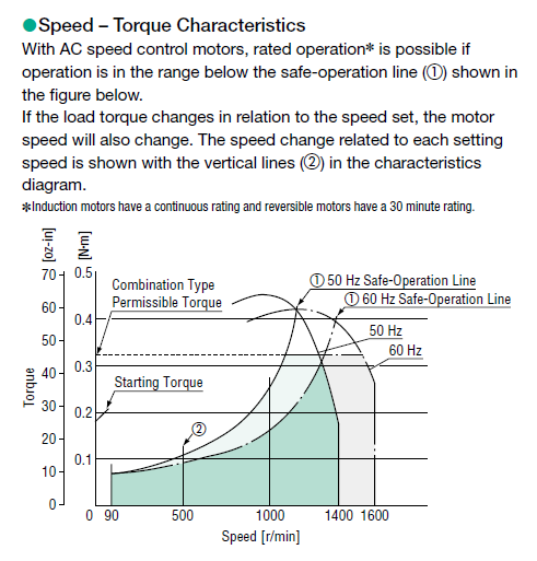
Now let's look at another speed control method. Take a look at a single-phase AC induction motor's speed torque curve, which describes what a motor will do once turned on. The motor will start at 0 r/min, then accelerate up to its rated speed. Notice how the input voltage affects the shape of the speed-torque curve. If the load torque remains the same, and input voltage is decreased from 100V to 90V, then the motor speed is reduced. Yes, you can use voltage to control the speed of an AC motor.
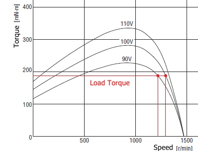
NOTE: top speed is ~1500 r/min because the input power is at 50 Hz. For 60 Hz motors, the 1500 r/min would be 1800 r/min.
However, you can see that the speed doesn't decrease by much with a 10v drop in voltage. If the voltage is decreased too much, the motor may be forced to operate in the unstable region (less than ~1,000 RPM) and possibly stall. Ideally, you'd actually want the motor to operate at its optimal rated speed for the best and most efficient performance. This speed control method is very similar to the speed control method of DC brushed motors. However, the speed control RPM range is much wider on DC brushed motors.
For this control method to be successful, a feedback device is necessary to closed the loop between the motor and speed controller. This feedback is necessary to keep the motor speed (and input voltage) from fluctuating too much.
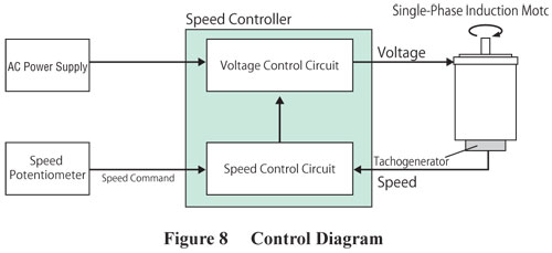
Oriental Motor uses tachogenerators to close the loop between our AC speed control type motors and speed controllers, such as the DSC Series or US2 Series. A tachogenerator, AKA tachometer, generates a voltage that's proportional to speed. It is used in a continuous feedback loop in order to maintain the speed accuracy at ±1% or less.
This is a simplified control circuit diagram for the DSC Series.
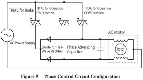
For anyone that's interested, this is the control circuit diagram with more details. You can see we use a TRIAC to control the voltage. We also use a half-wave rectifier.
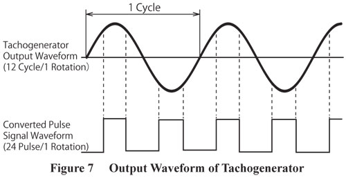
This shows how the tachogenerator is used during motor operation.
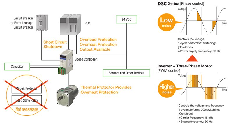
Since the control circuit is much less complex than a VFD, AC speed control motors are a cost-effective option vs VFD-driven AC motors. The phase control method also exhibits less electrical noise when compared to VFD-driven motors, where VFDs switch at a much faster rate.
Another advantage that was introduced with the DSC Series is vertical operation. In the past, tachogenerator motors were trouble for vertical travel applications. The reason is gravity.
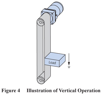 |
In this example, a motor is driving a load downward on a belt conveyor. As the load lowers, gravity will pull the load downwards and increase its speed. As the speed increases, the tachogenerator voltage increases. This makes the speed controller think that the motor is traveling too fast, thus decreasing its voltage to attempt to lower the speed. However, as the voltage decreases, the motor loses torque. This process repeats until the motor's torque is depleted, and the load drops. In the DSC Series, the Deceleration Stop function allows a controlled deceleration with automatic electromagnetic braking. |
A drawback of AC speed control motors with tachogenerator feedback is that at low speeds, the motor has certain limitations on torque. The motor's speed torque curve is labeled to show this. Make sure to operate below the "Safe-Operation Line". For the combination types (geared motors), please refer to the dotted line labeled "Combination Type Permissible Torque".
In other words, in order to avoid this issue, use a geared motor.
To learn more about the DSC Series, or its speed control method, please read the white paper.

Please subscribe at the top right corner of the page!
| Is There Another Alternative? | ||||||
|
If lower temperature operation, higher power efficiency, better speed regulation, constant torque output, or wider speed range is desired, For applications such as dual belt conveyors, polishing/deburring machines, or stirring machines, too much speed fluctuations due to load can affect the final product. If constant torque and speed regulation are critical, and servo motor systems are out of the budget, brushless motors are worth considering.
Click below for a comparison between the 3 speed control technologies available.
|