In this post, we will explain how the two drive systems, square wave drive and sine wave drive, can affect motor torque performance.
|
Drive Systems and Motor Torque |
A sine wave drive system has smaller torque ripples than a square wave drive system and allows for smoother operation.
Let us consider the reasons for this using the principles of motor torque generation. The ideal driving method for a motor is one that operates such that the magnetic flux and coil current are always orthogonal to one another in accordance with Fleming's Left-Hand Rule, as shown in Fig. 2.2. This driving method applies to all motor types. In DC brushed motors, this is done through mechanical commutation. To explain the principles of torque generation for brushless motors, we will use a simplified three-phase, 2-pole model as shown in Fig. 3.4.
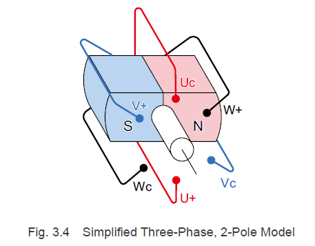
Rotors contain a rotational axis in the center between the north and south poles. In the stator that surrounds the rotor magnets, phase-U, phase-V, and phase-W coil windings are offset 120° from each other.
U+, V+, and W+ are connected to the drive circuit, and Uc, Vc, and Wc are connected at one point (common). Here, we will designate the direction that flows from the drive circuit to the common as "plus" and the direction that flows from the common to the drive circuit as "minus".
Let us take a detailed look at the coils of a particular phase. As you can see from the state of the coil and rotor magnets in Fig. 3.5, the rotor and stator positions are the opposite of what they would be in a DC brushed motor. If a current flows at this point, as shown in Fig. 3.5, a downward electromagnetic force will be generated on the south pole side, and an upward electromagnetic force will be generated on the north pole side, as determined by Fleming's Left-Hand Rule. However, because the coils in a brushless motor are fixed, a reactive force acting on the rotor magnets turns the rotor clockwise.
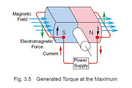 The electromagnetic force F[N] that acts on the windings in the state shown in Fig. 3.5 is calculated using the below formula that was explained in the DC motor rotation principles section.
![Electromagnetic force F[N]](https://blog.orientalmotor.com/hubfs/image-png-Jul-27-2021-12-35-13-39-AM.png)
However, if the rotor rotates and assumes the state shown in Fig. 3.6, the electromagnetic force F that acts on the conductor is generated in the direction that extends the coil toward the outer side, so no force (torque) is generated toward the rotor magnets in the rotation section.
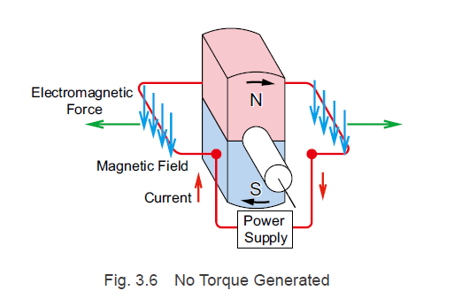
In other words, with respect to the conductor, the direction of the magnetic flux density B that acts as torque is orthogonal to the rotation axis and changes according to the rotation angle of the rotor magnets.
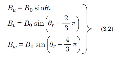
When the rotor has rotated, it is assumed that the magnetic flux density that acts as torque on the coils of the phase-U, phase-V, and phase-W, which are offset from one another by 120°, changes into a sinusoidal form.
When it has rotated clockwise with the rotor angle shown in Fig. 3.4 at 0° and the maximum magnetic flux density as B0, the relationship between the rotor angle and the magnetic flux densities of the phases, represented as Bw, Bv, and Bw, are represented by Formula (3.2).
3.2.1 For a Square Wave Drive System
To explain the motor torque when using a square wave drive, we will use a simplified three-phase, 2-pole model as shown in Fig. 3.4.
Driving Current
For brushless motors with a square wave drive system, as explained in "2.2.2 Brushless Motor Rotation Principles", current flows to the coils in phase-U, phase-V, and phase-W according to the excitation patterns from the rotor angles detected by the magnetic pole sensor.
If there is a clockwise rotation with the rotor angle shown in Fig. 3.4 at 0° and the motor current as im, the relationship between rotor angle and the phase currents for each of the phases is as indicated in Fig. 3.8.
At this point, when the rotor angle is between 30° and 150°, the current flowing through the phase-U is im, and between 210° and 330°, it is -im. The currents for the phase-V and phase-W experience a phase delay of 120° and 240°, respectively, with respect to the phase-U current.
Motor Torque
The torque T generated by each of the phase coils is calculated using the electromagnetic force F and the distance r from the center of the rotor rotation to the conductor.
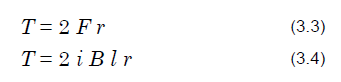
Thus, the motor torque is the sum of the torques generated by the coils in each of the phases, and it is represented by the following formula.
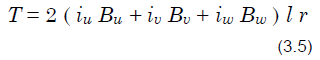
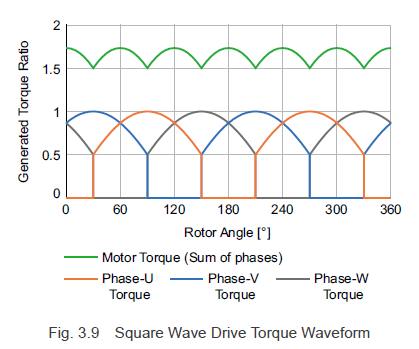
If r, l, im, and B0 are set to 1, and the torque for each phase is calculated from the current and magnetic flux density for each rotor angle using Formula (3.2), Fig. 3.8, and Formula (3.5), the result is the torque waveforms shown in Fig. 3.9. Because 6 torque ripples are generated for each rotation, speed ripples are generated during low speed rotation.
3.2.2 For a Sine Wave Drive System
To explain the motor torque when using a sine wave drive, we will use a simplified three-phase, 2-pole model as shown in Fig. 3.4.
Driving Current
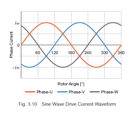
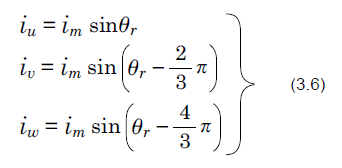
When the rotor has rotated clockwise, a sinusoidal current with a phase difference of 120°, as shown in Fig. 3.10, flows to the coils of the phase-U, phase-V, and phase-W, which are offset 120° from one another. In Fig. 3.4, if there is a clockwise rotation with the rotor angle at 0° and the maximum value of the current at im, the currents for each phase, denoted as iw1, iv1 and iw1, are represented by Formula (3.6).
Motor Torque
Just as with the square wave drive, the motor torque is the sum of the torques generated by the coils in each of the phases, and it is calculated using Formula (3.5).
In addition, Formula (3.5) can be simplified using Formula (3.2) and Formula (3.6) as shown below.
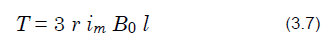
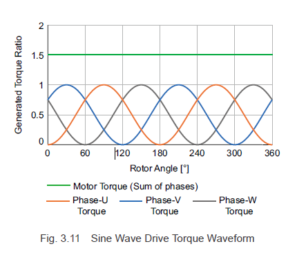
If r, l, im, and Bo in Formula (3.7) are set to 1, and the sum of products for the current and magnetic flux density for the phases for each rotor angle is calculated, the result is the torque waveforms shown in Fig. 3.11. In Formula (3.7), the term for the rotor angle Θ disappears, and the motor torque in Fig. 3.11 is constant. In other words, with a sine wave drive, there are no torque ripples in any rotation, and smooth operation is possible during low speed rotation.
For the best performance, Oriental Motor's brushless motor drivers employ the sine wave drive method.
|
Previous Post
|
Next Post
|


Learn more about Oriental Motor's 
Subscribe (top right corner) to receive monthly updates!