Proper sizing of a motor requires that 3 criteria must be met: torque, load inertia, and speed. For the first part of this Motor Sizing Basics series, I will be explaining what load torque is, how to calculate it for specific application examples, and how it fits into the torque requirement for the application.
| What is Torque? |
Torque is defined as rotational force at a distance from the rotational axis. It is measured by units such as lb-in (pounds inch) in imperial or Nm (newton metre) in metric. Torque is just as important, if not more important, than the horsepower of a motor. Horsepower is how fast the work can be done and is calculated with torque multiplied by speed. In other words, torque is the capacity to do the work, and power is the speed at which the work can be done.
| What is Load Torque? |
Torque has 2 main components: load torque and acceleration torque. Load torque is the amount of torque constantly required for application and includes friction load and gravitational load. Acceleration torque is the torque required just for the maximum acceleration and deceleration rate for the load. The faster the load needs to accelerate, the higher the acceleration torque is. Sometimes the load torque is higher; sometimes the acceleration torque could be higher. It's important to calculate both; especially for quick motion profiles.
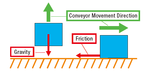
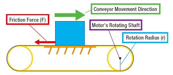
In the above image, we show several arrows which depict the direction of forces that are interacting in this application. Which do you think is load torque? The answer is both.
Load torque is the sum of both friction and gravitational loads. The gravitational force is determined by the weight, or mass x gravitational acceleration (g). The friction force, acting in the opposite direction as the conveyor movement direction, is calculated by multiplying the mass of the load with the friction coefficient of the 2 surfaces: m x µ.
Load torque calculation is different for various applications. Let's take a look at some common examples to see how the load torque is calculated.
| Example: Pulley Drive |
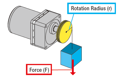
For a pulley drive application, the load torque calculation is pretty straight forward. We need to generate a force at some distance away from the motor shaft (definition of torque). This can be calculated by multiplying force (F) by the rotation radius (r). In order to move the load (blue box), the motor must generate more torque than this value.
To calculate load torque, multiply the force (F) by the distance away from the rotational axis, which is the radius of the pulley (r). If the mass of the load (blue box) is 20 Newtons, and the radius of the pulley is 5 cm away, then the required torque for the application is 20 N x 0.05 m = 1 Nm. Typically, a safety factor is used so that the motor generates more torque than required to accommodate any inaccuracies in variables used for calculation.
|
Here's the formula to calculate load torque for a pulley drive with all the variables:
|
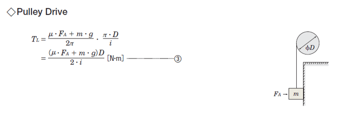
The above formula works for applications with friction load or without. If you remove friction from the system (friction coefficient of sliding surface µ = 0; external force FA = 0; gear ratio i = 1), you essentially end up with the same basic formula of force (F) x radius (r).
Now let's try to apply this concept in another application that deals with friction.
| Example: Conveyor |
In a conveyor application where the load is supported by a surface, friction is constant and is proportional to the load's mass. The degree of slip on the contact surface, or friction coefficient (µ), is necessary to determine friction force (F).
|
The following formula is used to calculate load torque for belt drives (conveyors) as well as rack and pinion drives.
|
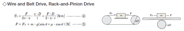
For this type of application, we'll need to calculate force (F) first before we can calculate the load torque (TL). This requires us to determine the variables external force (FA), mass (m), and inclination angle (Θ). Once we have the F value, then we can plug it into the load torque (TL) formula.
| Example: Rotary Index Table |
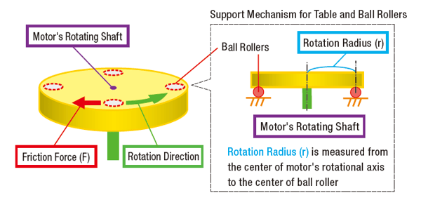
Load torque calculation for rotary index tables uses the same formulas as a belt drive, but it requires a slightly different thought process to determine the necessary variables. In this case, friction occurs at points where the ball rollers (support bearings) and the table make contact, so radius (r) will be the distance from the center of the motor shaft to the contact point between the table and its support bearings. The mass (m) will be the mass of the table plus load(s). The friction coefficient (µ) is typically found in the specifications of the bearings.
|
TIP: Motor sizing tips |
|
1. Be careful not to mix and match imperial units and metric units in the same formula. 2. If you need to convert units, make sure it's converted properly; especially the decimal point.* 3. Use adequate safety factor(s). You'd rather oversize than undersize the motor. 4. It helps to have another fresh set of eyes to double check your calculations. *Use a |

However, load torque is just one of two components of the total torque required for the application. For proper motor sizing, we still need to calculate for acceleration torque, load inertia, and speed.
In the next few posts, I will go over calculations for load inertia, acceleration torque, speed, and axial/radial loads. Better get comfortable.


|
TIP: Is there an easier way to size motors? |
|
For the most common applications, motor sizing calculators are offered from motor manufacturers where you can simply plug in values to quickly calculate the results. A deeper understanding into motor sizing equations is still necessary for more complex applications. Example: Lead/ball screw
|